Actuator is a critical mechanical-electronic component that makes the opening-closing operations of industrial valves fully automatic without the need for manual labor. It is directly mounted on the valve body and performs both "fully open/closed" (on-off) and intermediate position controls precisely. In traditional handwheel or lever system control methods, operator error, time delay, and work safety risks are high; with actuators, these risks are minimized, and operational speed and repeatability are significantly increased.
The basic working principle of the actuator is to convert the signals received from the control system (PLC, DCS, or SCADA) into electrical, pneumatic, or hydraulic energy and transmit them to the valve shaft via gear, piston, or diaphragm mechanisms. Thus, the valve shaft is moved to the desired angular position within seconds. The adapter arms and flanges used during installation ensure mechanical compatibility between the actuator and the valve body; thus, torque transmission is realized without loss and safely.
Modern actuators have limit switch boxes, inductive sensors, or analog positioners that provide position feedback. These elements transmit the current position information of the valve to the control system as a 0–10 V or 4–20 mA signal. Therefore, instant status tracking is possible even when the opening-closing operation is completed or in intermediate positions. In case of power outages, emergency shutdown (fail-safe) springs or battery systems integrated into the circuit ensure that the valve moves to a safe critical position (usually closed).
Another advantage of using actuators is the reduction of maintenance and operating costs. Considering the labor and risk required for manually operating large-diameter valves; systems commissioned with actuators increase personnel efficiency and facilitate long-term maintenance planning. Additionally, by choosing certified actuators within the scope of industrial automation standards (IEC 61508, SIL requirements), process safety and compliance can be ensured.
In conclusion, the correct selection and installation of actuators in automation projects maximize speed, precision, and safety in process control. Actuators, by combining the mechanical control of the valve with electrical or hydropneumatic signals, make a significant contribution to the uninterrupted, safe, and efficient operation of industrial facilities.
Working Principle and Design Components
Electric actuators perform the opening and closing operations of the valve through the electric motor, gearbox, and control card they contain. The motor type can usually be AC or DC; both types are selected according to different voltage and power requirements. A direct gear reduction mechanism converts the high rotational speed of the motor into a low, high-torque output and transfers it to the valve shaft.
This design ensures reliable torque transmission even under heavy-duty conditions. Additionally, aluminum or stainless steel is mostly used as the body material to provide both lightness and corrosion resistance.
Precise Position Control and Feedback
Modern electric actuators can directly read many control signals (4–20 mA, 0–10 V, digital protocols like Modbus or Profibus) and adjust the valve position precisely according to these signals. Thanks to the potentiometer, encoder, or LVDT (Linear Variable Differential Transformer) sensors integrated into them, instant feedback is possible. Thus, instant position information is sent to the control system; when any deviation is detected, the actuator makes corrections within itself. Limit switch boxes can be mechanical or electronic and provide definite signals for "fully open" and "fully closed" positions.
Inverter-Supported Speed and Torque Adjustment
Electric actuators gain a flexible structure that allows both rotational speed and torque limitation by being fed with frequency inverters (VFD) or servo drivers. Thus, the valve opening/closing time can be optimized according to process conditions; while speed is increased in applications requiring fast cycles, soft start and stop profiles can be defined in systems requiring vibration sensitivity. At the same time, energy consumption can be reduced, and overloads can be prevented.
Ease of Integration and Compatibility with Automation Systems
Electric actuators can be easily integrated into PLC or SCADA systems. Thanks to standard industrial communication protocols, remote control and monitoring can be performed from the central control room or distributed control systems. I/P converters mounted on the panel convert the electrical control signal into pneumatic pressure, allowing them to be used in hybrid (electro-pneumatic) architectures. Additionally, extra interlock controls or SIL (Safety Integrity Level) certified modules can be added to add a security layer when needed.
Low Maintenance Requirement and Long Life
One of the biggest advantages of electric actuators compared to pneumatic or hydraulic systems is that they do not contain hoses, valves, or sealing elements that may leak. Lubrication points usually consist of bearings and gears filled with grease for life; thus, they do not require additional maintenance other than simple checks performed once a year. The windings of electric motors and control cards have protections against overheating. Cooling channels or extra fans mounted on the body prevent performance drop even in hot environments.
Application Areas and Selection Criteria
Electric actuators are an ideal solution, especially in medium and small diameter valve lines, clean facilities, and systems with low maintenance expectations. They are widely used in water treatment plants, HVAC applications, chemical processes, and power plants. Points to consider when making a selection are:
• Torque Requirement: The required output torque should be calculated according to the valve size and operating pressure.
• Speed and Cycle Frequency: If the number of cycles is high, inverter-supported models should be preferred.
• Environmental Conditions: Appropriate IP/SIL protection class should be selected against humidity, dust, explosive or corrosive chemicals.
• Feedback Type: Is analog feedback sufficient, or is a digital encoder necessary?
• Integration Protocol: Options like Modbus, Profibus, HART should be evaluated for PLC/SCADA compatibility.
Electric actuators are indispensable equipment of industrial automation with their energy efficiency, ease of maintenance, and precise control capabilities. With the right model and hardware configuration, process efficiency and operational safety of facilities can be maximized.
Performance and Durability in Pneumatic Actuators
Working Principle and Design Types
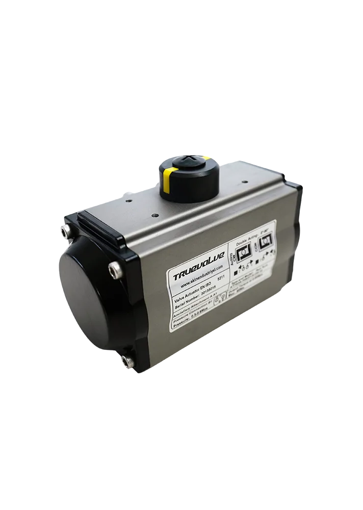
Pneumatic actuators control the valve with the force applied by compressed air on the piston or diaphragm. They are divided into two main groups as single-acting (spring-return) and double-acting models. In double-acting types, compressed air provides both opening and closing movements; since no spring is used, they offer ideal performance at high cycle speeds. In single-acting actuators, the spring mechanism pulls the valve shaft back to the safe position (usually closed) when the air is cut off; this "fail-safe" feature is preferred in critical applications for process safety.
High Cycle Durability and Fast Response Times
One of the most important advantages of pneumatic systems is that they offer opening and closing times in seconds. In actuators with metal or elastomer diaphragm designs, shaft movements occur with millisecond delays thanks to the fast passage of valves directing air flow. Additionally, lubrication additives in the air minimize friction and reduce wear rate. Thus, even after millions of cycles, performance loss remains minimal; maintenance intervals are extended in lines requiring frequent cycles, enabling uninterrupted production.
Prevention of Spark Risk in Hazardous Environments
In facilities containing chemicals, oil, gas, and explosive dust, electrical equipment carries the risk of creating sparks. Pneumatic actuators eliminate this risk from the root by using only compressed air instead of an electric motor or coil. ATEX or IECEx certified models provide full compliance with explosive environment standards with additional safety measures. Mechanical wear caused by dusty and corrosive gases is also controlled with surface coatings and specially alloyed piston materials; thus, both high safety and long service life are achieved.
Energy Efficiency and Cost Advantage
In facilities with an existing compressor infrastructure, the installation of pneumatic actuators can be quickly implemented without requiring extra investment costs. Unlike electrical systems, there are no initial inverter and motor costs; additionally, compressed air can feed more than one actuator on the same line if necessary. Air consumption is optimized with pressure regulators and flow control valves; energy efficiency is increased by reducing unnecessary pressure drops. This means long-term savings in operating expenses.
Easy Integration and Simple Maintenance Processes
Pneumatic actuators are controlled with 3/2 or 5/2 way solenoid valves that can be directly connected to classic control panels. These solenoid valves easily integrate with PLC or DCS systems with low current draws and fast response times. Different position feedback options (limit switch, NAMUR sensors) are available, and the valve status can be monitored with analog or digital signals. Maintenance needs are limited to routine checks of the filter-regulator-lubricator (FRL) unit, inspection of connection leaks, and monitoring of air quality (oil, moisture, particles). These simple maintenance procedures maximize the facility's uptime while eliminating the risk of unplanned shutdowns.
The fast response, high cycle durability, environmental and explosion safety, energy efficiency, and user-friendly maintenance processes provided by pneumatic actuators offer indispensable solutions in critical sectors such as chemicals, food, and pharmaceuticals. With the appropriate model and material selection according to your application requirements, you can establish a long-lasting and reliable automation infrastructure.
High Power Applications with Hydraulic Actuators
Hydraulic actuators are powerful and reliable components that control valves using the intense force provided by high-pressure oil flow. These systems stand out with their ability to perform seamlessly even in massive valve bodies and heavy-duty conditions. Hydraulic actuators, preferred in processes requiring both high torque and stable movement; offer features that are extremely efficient in terms of energy transmission, minimize vibration, and extend maintenance periods.
High Torque and Pressure Capacity
The incompressible nature of the oil used in hydraulic actuators allows for high force production in a small volume. Thus, even in applications carrying heavy loads such as large diameter flow control valves or industrial piping systems, a torque value that can perform the shaft rotation within seconds is obtained. Hydraulic cylinders that can meet peak torque needs reach power levels that electrical systems cannot access, so body designs equipped with materials resistant to high pressure are of critical importance.
Stability at Low Speed and Vibration Control
In heavy-duty applications, sometimes the valve needs to be positioned slowly and controlled. Hydraulic actuators provide smooth and jerk-free movement even at low speeds thanks to the viscosity of petroleum-based hydraulic oil. This control is optimized with pressure-sensitive flow control valves and servo-directive pump systems; therefore, while the valve makes a smooth transition to the exact desired position, wear caused by mechanical vibration is minimized.
Resistance to Harsh Environmental Conditions
The closed-circuit structure of hydraulic systems allows isolation from the external environment. Even in dusty, humid, or chemical vapor-containing environments, system performance is maintained for a long time thanks to sealing elements and special gasket materials. Additionally, hydraulic hoses and connection components designed against high temperatures and impacts facilitate maintenance planning even under harsh operating conditions.
Integrability into Critical Process Control
Hydraulic actuators can be controlled with electrical signals or automatic valve blocks according to the demands of process automation systems. When integrated with pressure transducers and flow sensors, instant data is transferred to SCADA or DCS control rooms. Thus, process safety is increased by observing both temperature, pressure, and flow rate parameters, and early intervention is offered.
Long Life and Easy Maintenance
The continuous filtration of hydraulic oil and regular control of the system's pressure balance minimize wear and extend the life of components. Samples taken to monitor oil quality during maintenance are analyzed with particle counting and water content measurements. Hose and gasket replacement needs are predetermined with planned shutdowns, preventing unexpected failures. Additionally, the modular structure of sensors and valve blocks allows for quick intervention in the field.
Application Examples
– Petrochemical Plants: Safe shutdown and commissioning operations in high-pressure reactor lines are provided with hydraulic actuators. – Power Plants: Critical valve operations in steam lines and cooling circuits are carried out with hydraulic systems due to high torque requirements. – Maritime and Offshore: In valve control under dynamic loads such as waves and wind, hydraulic actuators resist vibration and impact effects.
In conclusion, hydraulic actuators stand out as the first choice in heavy-duty applications with their high power, precise control, resistance to harsh conditions, and long life advantages. If your projector requirements are large diameter valve control, high torque, or critical process safety, hydraulic actuators offer the performance and reliability that will satisfy you.
Actuator Integration in Industrial Automation
One of the cornerstones of industrial automation is ensuring that field devices—especially actuators—communicate with control systems completely and reliably. Proper integration not only performs the opening-closing or adjustment operations of the valve but also offers critical contributions in terms of process sustainability, safety functions, and energy efficiency.
Mechanical Layout and Installation Details
The integration process begins with the installation of the field device. Before the actuator is connected to the valve body, mechanical compatibility must be ensured with suitable adapter and flange sets. During installation, shaft alignment, torque arm length, and the tightness of connection elements should be checked; incorrect alignment can lead to vibration, wear, and high insulation resistances. In field cabinet or type 4 case installations, explosion zone class-compliant connection glands, gaskets, and grounding points should be used for cable entries.
Signal Conversion and I/P Solutions
The automation system usually produces a 4–20 mA current signal or a 0–10 V voltage signal. While this signal is sent directly to electric models in actuator control, I/P (Current-to-Pressure) converters come into play in pneumatic or hydraulic actuators. The I/P converter converts the input current signal into a pressure signal, for example, 0.2–1 bar or 3–15 psi. The selected I/P unit should be evaluated according to speed response, accuracy tolerance, temperature compensation, and filtration features; it has a direct impact on the performance of the control loop.
Limit Switch Boxes and Safety Layers
The fully open or fully closed positions of the actuator are monitored with mechanical or inductive limit switch boxes. These boxes usually contain more than one switch; one gives the "fully open" signal, and the other gives the "fully closed" signal. Additionally, for emergency scenarios, systems that integrate a "fail-safe" spring mechanism or move the valve to a safe position (usually closed) in case of a power outage are integrated. This safety layer ensures that the process control system (PCS) works in harmony with the Safety Instrumented System (SIS) and helps meet the relevant SIL (Safety Integrity Level) requirements.
Precision Adjustment Capability with Positioner Use
Positioner devices receive the desired valve position command and control the consistency of the air or electrical signal applied to the actuator with the actual position. The positioner automatically corrects the deviation (offset) by analyzing the feedback signal; this offers high precision, especially in applications requiring proportional control, such as flow, pressure, or temperature regulation. Digital positioners enable two-way communication with central systems via HART, Foundation Fieldbus, or Profibus PA protocols, allowing real-time reporting of field data.
Communication Protocols and Network Architectures
In addition to traditional analog signals, modern actuators often support digital fieldbus protocols. While HART provides digital data flow over the 4–20 mA line, fully digital networks like Foundation Fieldbus or Profibus PA can gather many devices on a single cable. This reduces cable costs and allows remote diagnostics and configuration operations. In smart actuators supported by Ethernet/IP or Profinet, high-speed communication and deterministic data transmission offer cycle times at the microsecond level.
SCADA and DCS Integration
Integration into SCADA (Supervisory Control and Data Acquisition) and DCS (Distributed Control System) platforms in the central control room allows monitoring of field signals on the graphical interface, alarm-message management, and trend records. Manual override authority can be granted through operator panels, as well as transition commands to automatic control scenarios. Additionally, high-level functions such as soft start/stop or batch process management are synchronized with position feedback at the actuator level.
Commissioning, Calibration, and Continuous Monitoring
During the commissioning of the field device, loop check tests, quick open-close tests, and positioner calibration should be performed. Calibration steps should be adjusted according to minimum and maximum signal values, and the accuracy of the feedback should be checked. During operation, diagnostic data (such as food oil pressure difference, motor amperage, position deviation) is regularly collected and analyzed on digital twin or cloud-based platforms. Abnormalities are detected early, and preventive maintenance timing is optimized.
Energy Efficiency and Green Process Approaches
Proper integration also ensures minimizing energy consumption. When transitioning from analog signal control to digital positioner use, air or electricity consumption is optimized; unnecessary valve movements and excessive pressure consumption are prevented. Additionally, thanks to emergency valve blocks and by-pass lines, changing the valve position quickly but controlled during process shutdowns contributes to energy efficiency.
Actuator integration in industrial automation is a detailed process that encompasses many steps, from mechanical installation to digital communication. The harmony between the field and control layers is directly determinative in terms of process safety, energy efficiency, and operational continuity. With proper planning, appropriate device selection, and meticulous commissioning applications, it is possible to achieve both safety and efficiency goals in your facilities.
Evaluation of Application Requirements
Before determining the type of actuator, the basic parameters of the process should be carefully examined. Valve diameter, operating pressure, fluid type, and operating temperature directly affect the required torque and speed values. For example, low-torque electric actuators are sufficient for small diameter valves, while stainless-bodied or ex-proof certified pneumatic models may be preferred in environments containing high temperatures or corrosive chemicals. In lines requiring high-frequency cycles, the fast response times of air systems come to the fore.
Adaptation to Environmental and Operational Conditions
Environmental and operational conditions are elements that need to be carefully evaluated in advance for actuators to work long-lasting and reliably. High humidity, dirty air, and dust particles can penetrate the actuator body and cause wear on mechanical parts, while corrosive chemical vapors can quickly wear out seals and seal surfaces. Therefore, during field analyses, the amount of humidity and dust in the environment, the type and concentration of chemical agents it contains should be determined, and stainless steel, aluminum alloy, or high-performance coated surfaces suitable for these findings should be preferred for the actuator body. Choosing seal materials from elastomers such as EPDM, Viton, or PTFE, suitable for the chemical environment they will be exposed to, greatly increases the sealing life and system reliability.
When hazardous area classification is made for electrical equipment in the field, ATEX or IECEx certified actuators should be used, especially in areas with the risk of explosive gas or dust clouds. These certifications guarantee that the device will operate without producing sparks and generating high temperatures, ensuring both personnel safety and elevating process safety to the highest level. Cable glands and junction boxes also need to be certified to the same standards to eliminate the smallest electrical leakage and spark risk that may occur in explosive environments.
Vibration and mechanical impacts can cause microscopic cracks to spread rapidly in actuator gears and bearings. To reduce this risk, the use of flexible couplings and vibration pads during installation prevents vibration from being directly transmitted to the shaft and extends the life of the components. Similarly, elastomeric pads used in connection flanges balance impacts and reduce mechanical stress by tolerating small alignment errors on mounting surfaces.
Proactive maintenance and monitoring systems also play a critical role in challenging field conditions. Integrating sensors that detect ambient temperature, humidity, and vibration levels onto the actuator collects real-time diagnostic data and sends automatic alerts to maintenance teams. Periodic scans with thermal cameras detect overheating areas or leaking seal points early. This reduces the risk of unplanned shutdowns and keeps maintenance costs under control.
In conclusion, addressing environmental and operational conditions with a holistic approach during actuator selection and field integration; using suitable materials, certification, vibration isolation, and advanced monitoring systems ensures long-lasting, uninterrupted, and reliable performance even in the most challenging industrial environments.
Load and Cycle Frequency Analysis
The annual cycle count of the actuator should be calculated within the framework of process requirements. While simple spring-return single-acting pneumatic models can be preferred for low-cycle operations; lubrication life, piston design, and gear type should be examined in detail for applications requiring one or more cycles per second. In electric actuators, the choice of gearbox type (helical, gear, or planetary reducer) directly affects torque density and maintenance interval.
Manufacturer and Certification Criteria
When choosing a reliable actuator supplier, reference projects, spare parts availability, and technical support should be considered. ISO 9001 quality management system, CE mark, and SIL certifications indicate that the product has passed testing processes and meets functional safety requirements. Additionally, the supplier's spare parts guarantee and training services reduce long-term operating costs.
Installation and Calibration Tips
Proper installation begins with the alignment of the actuator-valve. Shaft adapters, drive arm length, and flange connections should be adjusted according to the manufacturer's guide. After installation, positioner and limit switch box calibration is important to receive error-free fully open and fully closed signals. In I/P converters, temperature compensation and hysteresis settings increase control accuracy.
Periodic Maintenance and Monitoring Strategies
Maintenance periods should be created according to usage conditions, and the recommended lubrication and seal replacement intervals in the technical documents should be followed. The field maintenance form should include grease filling status of lubrication points, elasticity control of seals, temperature measurements, and the accuracy of feedback signals (4–20 mA or digital encoder data) to keep systematic records. Regular vibration and thermal camera checks show early wear signs.
Failure Preventive Maintenance and Remote Diagnostics
With Industry 4.0 approaches, diagnostic data from sensors integrated into actuators can be analyzed on cloud platforms. Pressure fluctuations, motor current changes, or position deviations can be interpreted with machine learning algorithms to provide a warning before failure. Thus, planned shutdowns are optimized, sudden interruptions are prevented, and maintenance costs are minimized.
Conclusion and Recommendations
In industrial automation, actuators are critical elements that directly affect process efficiency and operational safety by ensuring the precise and reliable management of valves. Electric actuators offer a clean and economical solution for medium and small diameter valves with the advantage of low maintenance needs and energy efficiency, while pneumatic models are indispensable in chemical, food, and pharmaceutical facilities due to their fast response times and lack of spark risk in explosive environments. Hydraulic actuators show superior performance in large valve applications requiring high torque and provide long-lasting control against harsh environmental conditions. When choosing between these three technologies, the process requirements, maintenance strategies, and investment costs should be evaluated together.
During the installation and integration phase, using the correct adapter and flange sets with expert engineering approaches, carefully aligning the shaft; the complete application of communication and feedback elements such as limit switch boxes, I/P converters, and positioner devices significantly improves system performance. Choosing compatible signal protocols (4–20 mA, HART, Profibus, etc.) used in the field both speeds up the commissioning process and facilitates long-term maintenance and expansion operations. Additionally, full integration with SCADA or DCS systems allows actuators to both monitor status and exchange data bidirectionally with the central control room, offering additional advantages in terms of early warning mechanisms and energy management.
Creating periodic maintenance policies and training field personnel on these issues is critically important to prevent unexpected shutdowns. Annual checks should include grease filling status of lubrication points, elasticity tests of seals,
accuracy of limit switch and positioner settings, I/P converter calibration criteria, and integrity of sensor signals. Additionally, with remote diagnostics and diagnostic data collection solutions, pressure fluctuations, motor current changes, or position deviations can be monitored instantly; this reduces maintenance costs and guarantees uninterrupted operation in the process.
In conclusion, determining the optimum solution specific to your facility by combining the speed, power, and precision advantages offered by actuator technologies increases system safety in the short term and reduces maintenance costs in the long term. As Ekin Industrial, we offer a comprehensive service with the determination of the appropriate actuator type, correct integration steps, trained field personnel, and advanced maintenance methods. If you aim for the highest efficiency and safety at every stage of your processes, you can contact our technical teams for detailed product and project consultancy.